Building a better Spray Booth
My original spray booth was built back in
the early 2000’s, when I was living in a house near Boston that had a pretty decent
basement. As I was still moving a lot at the time, one of my key requirements
was for something that was easily broken down for transportation. I also had
certain size limitations based upon where I was painting. Now that I am living
in a house where the space constraints aren’t as severe, I decided to upgrade
both the size and quality of my spray booth. Enter Spray Booth V2.0!!
Statement
of Caution/Liability: The information contained upon this page is
not intended to provide design information nor is it implied in any way shape
or form that this particular device is safe for any home use. I cannot guarantee my solution meets safety
standards, is safe, or actually evacuates harmful fumes. It is loosely based on U.S. OSHA standards,
but I again make no claims that it is safe.
It passes a common sense check, which means it may still be unsafe. Any electrical wiring should be done by
someone qualified to do so. This page is
intended only to document the solution that I have implemented which meets my
personal needs, and I recognize there are inherent risks with gaseous flammable
materials and electric motors which I am willing to accept. Anyone choosing to
use this information for their own purposes shall do so at your own risk.
Requirements:
Any “thing” that replaces another “thing” usually does so for a reason.
The main two failures of my old spray booth were tied to its number one
requirement: portability. First, I was utilizing an oven range hood for the
exhaust fan. Because this fan had a limited ~150 ft.³ per minute (CFM) rating,
it greatly limited the size of the booth if I were to adhere to the OSHA rules
regarding 100 linear feet per minute for safe airflow. The range hood was also
just dang heavy. As it sat on top of the booth, assembling the booth from time
to time became a chore. Further, the booth was an updraft design. It turns out
this is not a popular design for spray booth, as you are sucking the air across
and then up above the object you are painting. This introduces lots of opportunities
for dust, dried paint particles, or other mess to get dragged across the wet
paint surface, plus you are working against gravity. More commonly used paint
booth designs are either crossflow or down draft, where the air just go
straight across the object, or it is sucked into the floor of the booth which
keeps dust and other particles safely away from the wet paint. For V2.0 I chose
a crossflow design, with the inlet Plenum as low as possible on the backside.
Since I no longer have a requirement for portability, my first decision was to
size the exhaust fan. Once you have your exhaust CFM, you have determined your
inlet area and the size of your booth.
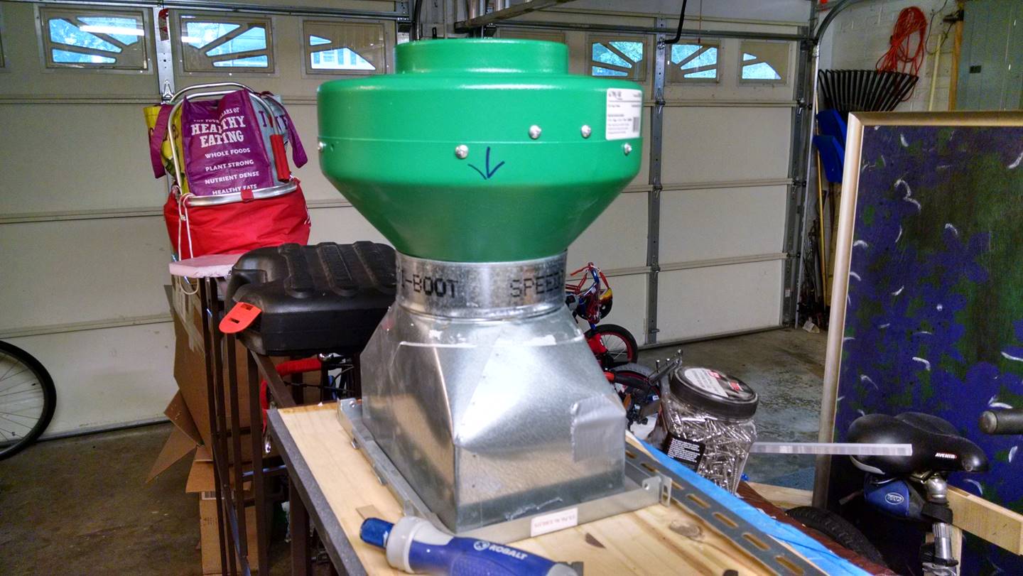
After
careful consideration, and evaluating several designs from Dayton blower I settled on the Hydrofarm Active Air 6 inch exhaust fan, rated at 400 CFM.
 My final decision wasn’t driven so
much by cost, but convenience. The Hydrofarm model is an in-line fan. While the
Dayton squirrel cage type design should be safer since the motor and electrical
components are out of the airstream entirely, I had planned to accommodate the
in-line fan and reduce any sort of fire or explosion hazard through filtration.
Again, this is the solution that works for me. The absolute safest method would
be to use a Dayton blower, but the right angle design of the Dayton exhaust fan
limited where could be placed in the airstream. I wanted to ensure the fan was
as far away from the spray booth as humanly possible for noise and to ensure
any flammable gases were thoroughly mixed well before they could possibly meet
the ignition source. The Dayton blower
would have to be mounted essentially on the backside of the spray booth.
My final decision wasn’t driven so
much by cost, but convenience. The Hydrofarm model is an in-line fan. While the
Dayton squirrel cage type design should be safer since the motor and electrical
components are out of the airstream entirely, I had planned to accommodate the
in-line fan and reduce any sort of fire or explosion hazard through filtration.
Again, this is the solution that works for me. The absolute safest method would
be to use a Dayton blower, but the right angle design of the Dayton exhaust fan
limited where could be placed in the airstream. I wanted to ensure the fan was
as far away from the spray booth as humanly possible for noise and to ensure
any flammable gases were thoroughly mixed well before they could possibly meet
the ignition source. The Dayton blower
would have to be mounted essentially on the backside of the spray booth.
Further,
in order for there to be combustion the stoichiometric ratio must be correct.
In layman’s terms, this is what people talk about when they mean a fuel mixture
is too rich or too lean. Too rich means not enough oxygen, fire won’t burn.
It’s like a perpetually flooded lawnmower. Too lean a stoichiometric ratio and
there isn’t enough combustible material in the gas to sustain ignition; the
molecules are simply too far apart. By virtue of having a fan putting out 400
CFM, and again limiting myself at worst-case to the output of a handheld spray
can, there simply isn’t enough ignitable material or gas passing through the
exhaust fan to ignite. In my opinion. By placing disposable furnace filters
across the exhaust Plenum, the vast bulk of ignitable dust in the form of dried
paint particles gets caught at the filter, well away from the exhaust fan which
is at the other end of a 20 foot long, 6 inch diameter flexible duct.
Booth
Sizing: In a
perfect world, a 400 CFM fan should accommodate a 4 ft.² opening— (400 ft.³ per
minute)/(4 ft.²) = 100 linear feet per minute through
the system. In reality, there are number of things which will reduce the flow
rate of the fan due to pressure drops in the system. I knew that there would be
at least two right turns coming out of the back of the booth as I wanted to run
the ducting out of the way along the roof of the garage.
I was
also pretty sure a 2’ x 2’ opening on the spray booth was substantially larger
than I wanted, so I needed to constrain the dimensions. I chose 24” wide as the
fixed dimension based on my previous booth limitations (wide is better than
tall) Sizing it to be 24” wide was a no brainer also from the ease of
construction viewpoint—there’s a lot of stuff cut in increments of 2 feet, such
as the Plexiglas sheets. Once I had that
locked in, the available flow rate locks in the height.
I knew I
was going to use (for cost purposes) flexible metal ducting. I made an initial
estimate of a 10% loss in volume flow rate based upon the flex ducting, but
balanced a little bit by how short a length of flex ducting I’m using—less than
20 feet. A 10% loss equates to losing 40
CFM, or dropping the overall outflow two 360 CFM, which would allow me to have
a 3.6 ft.² capture area and still meet hundred feet of air per minute going through
the system. Based upon this reduced number, I determined I wanted in inlet area
of 24” x 21”. This equates to a 3 ½ ft.² capture area, a tad below the 3.6 ft.²
Assuming the air is actually going through a 6” diameter pipe at 360 CFM, that
gives an average flow rate of 360 CFM divided by 0.19 ft.² = 1833 ft./m or 30.5 ft./s, which is roughly the velocity of air
traveling through an average vacuum cleaner.
This
picture gives an idea of the old booth versus the new based on the back walls:
Construction:
Like the original booth, V2.0 was to be built out of plywood sheets. I
had a number of these lying around from previous construction projects, as well
as a few that were used as packing material for a bathroom vanity. Waste not,
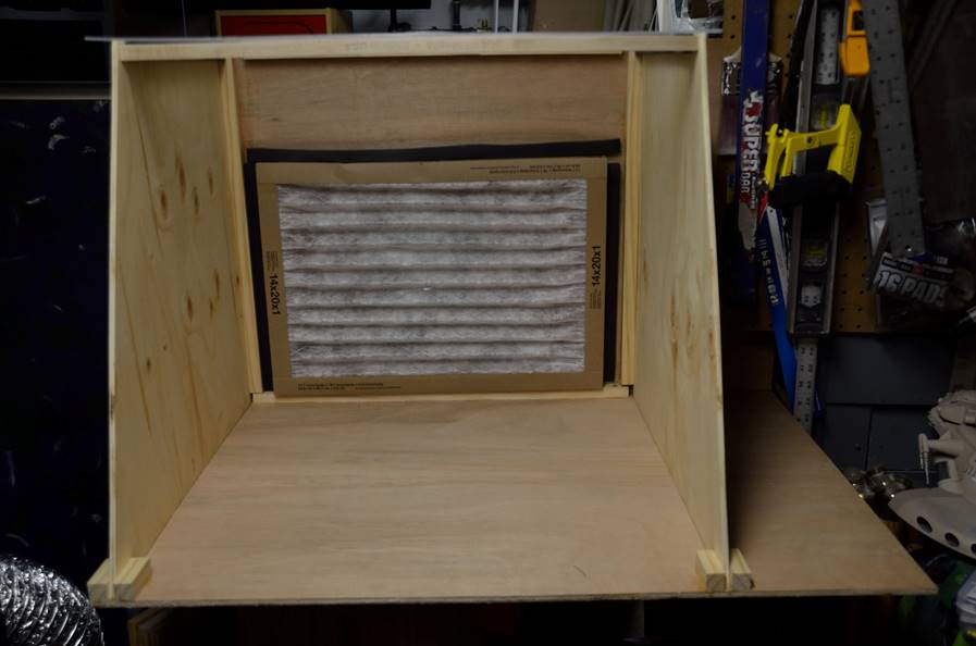
want not. I had learned a few lessons in operation from my previous one though,
that I wanted to incorporate into the new one. First, the filter to protect the
fan motor downstream. To keep it
affordable, I went with cheap furnace filters.
The 14”x20” filter is common, cheap, and covers the back wall/plenum
fine. The weather stripping holds it in
place and seals the edges, and when the fan comes on it gets sucked down fairly
tight.
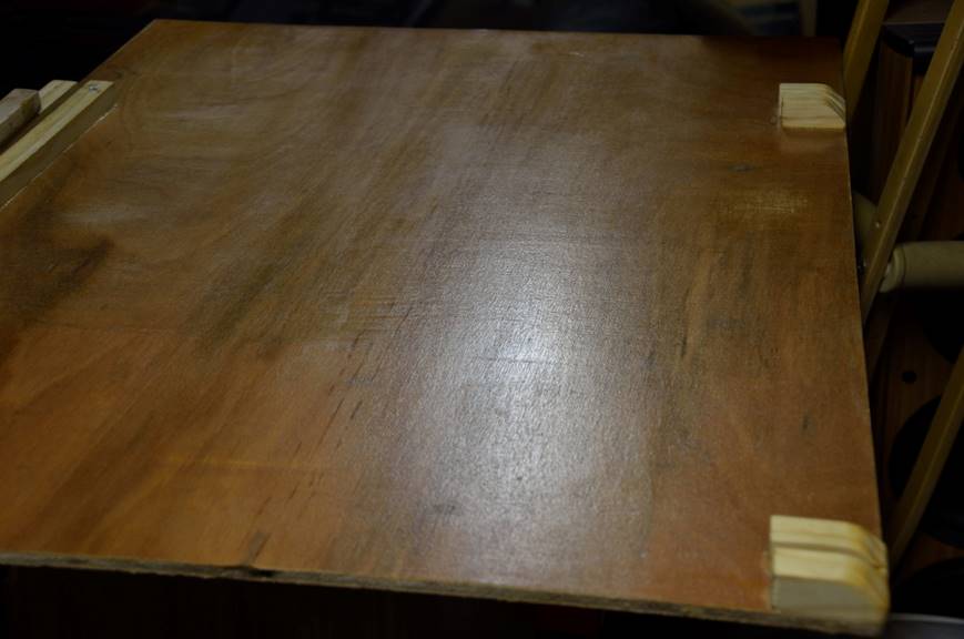
As you’d
expect these things get incredibly dirty over time with usage—note the back
wall above from the old one. There is spilled paint, there is of course the
overspray, and if the booth is just sitting out for a while it can gather a
significant amount of dust that is a pain in the butt to clean. I made the
decision early on to apply a clear polyurethane wood topcoat overall the
surfaces on the inside that may come in contact with paint. This has already
worked out very well; in my first use I had a significant paint splat that was
very simple to wipe up with a paper towel. The smooth polyurethane surfaces not
only were resistant to the paint thinner, they were smooth enough that they did
not shred the paper towel and introduce lint into the spray area.
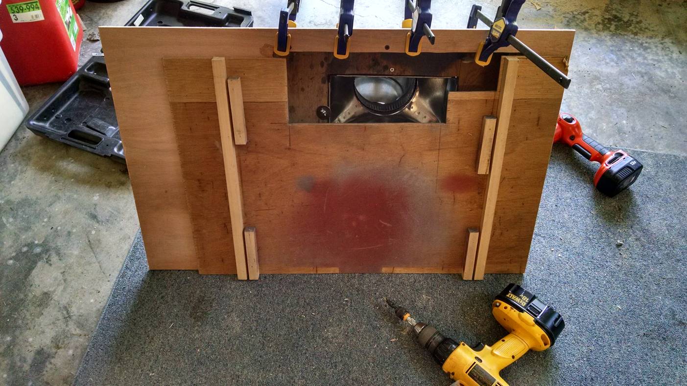
As I
previously mentioned, I wanted a cross draft booth, with the plenum as low as
possible. I built the plenum out of
scrap wood with a 3 ½” offset from the booth back wall, then transitioning
to 6” X 10” Speedi-Boot
square to round adapter (SBH-6106
SB). Speedi-Boots
aren’t cheap, but they are easy to bolt down and easy to seal up airtight. The plenum was sealed up tight with screws
and much construction adhesive.
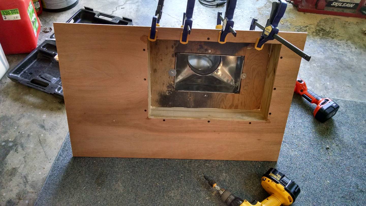
My original
booth had some useful features, such as hooks and pegs to hang items off of on
the side of the booth, as well as some shelf space on the outside of the booth
to put paint supplies. Being right-handed, I decided to incorporate the shelf
on the right-hand exterior side—which is why the plenum chamber is offset (and
upside down!) in the picture above. The
shelf is 8” wide, more because the oddball piece of plywood I had handy than by
design, but it worked out pretty well.
It is large enough to place my airbrush and cleaning station on, as well
as the Iwata SmartJet compressor I am using.
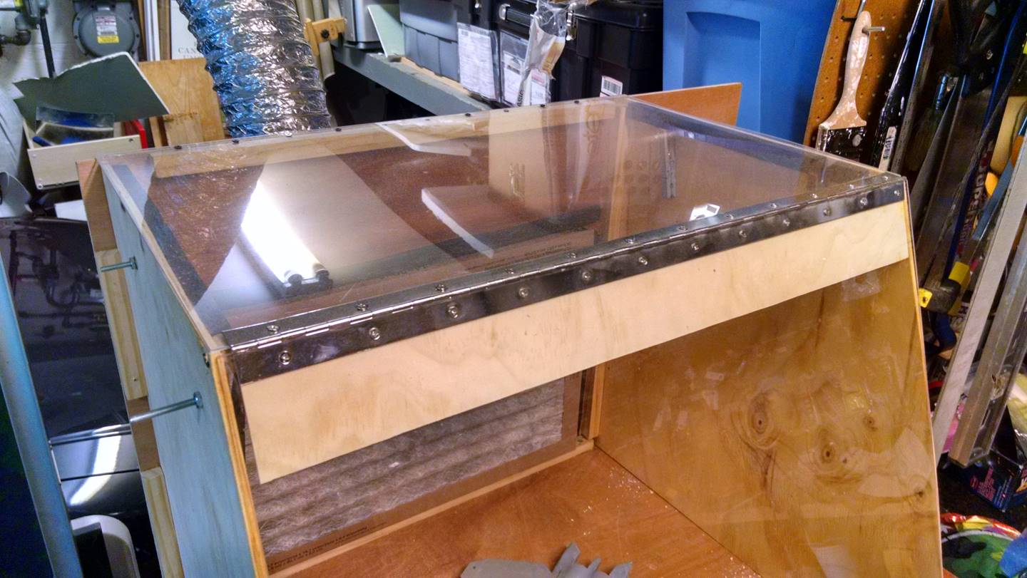
Lighting
on my original booth was also a problem.
Since the range exhaust hood sat on top of the booth, it had a very
limited light source to shine down upon the subject being painted. To take
advantage of as much natural lighting and top lighting as possible I decided to
make the top and the front door of the booth out of Plexiglas; the 2’ width
coming in handy again. It is relatively simple to place a florescent light
source of the appropriate color temperature on the Plexiglas top for as much
lighting as I need. Since the Plexiglas top and the door are pretty much out of
the airstream, they have tended to stay very clean and free of paint in usage. Unlike my prior model, I also wanted to have
some sort of door or way to close up the front. This would allow me to park wet
pieces in the booth and close the door, preventing dust from the garage
settling naturally onto the parts as they dried. It would also keep fumes down
after the fan was turned off. The door
was attached with piano hinge. I
pre-marked and drilled the Plexiglas, then screwed the hinge into a piece of
backing wood so the stress and odds of cracking the Plexiglas were minimized.
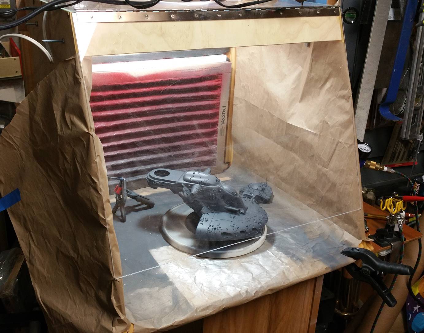
Fini!
Here’s
the final booth, in operation. It passed
the sniff test, in that there is no noticeable smell of paint fumes even with spray
cans when the fan is on. While loud, it
is still quiet enough to carry on a casual
conversation in the room. More importantly,
it doesn’t bother my family in the main house.
I have built-in some clothes pins on the interior of the booth to hold
large sheets of paper. The intent here is after a model is complete I can
simply remove the paper and take all of the old paint dust and residue out of
the booth. I’m currently using packing paper that came with some Amazon
shipments; when that runs out I could just as easily use excess Christmas
wrapping paper. There are additional places to clip or clamp the paper down
along the front edge of the booth, as the fan will easily suck the paper right
into the filter if it isn’t secured. You
can also see, just barely peeking around the corner, part of the Iwata SmartJet compressor on the right side shelf. The lighting is all ambient except on fluorescent
bulb on top pointing straight down. It’s pretty clear the down-and-across
airflow is working with gravity to keep paint dust down and away from the
model. All in all, I’m very pleased with
the results.
Now back
to building—and painting!
Questions? Shoot me a note.